A Volkwagen alternator needs a filament bulb to make the built in voltage regulator work right, so you can't just put an LED on it. I have a generic indicator light that I have been using. It's pretty common to put an LED indicator in parallel and put the LED on the dash. However, the voltage that lights the light is low enough that it wont light the LED on my speedometer. I will need to investigate, but in the mean time, I will put in a temporary switched 12V lead to my generic indicator because it won't charge without the bulb in place.
I replaced the "standard" electronic flash that I had with a flasher made for LEDs. Where the other flasher needs a load of about 1A to flash correctly, this one is rated for 20mA to 25A. It works perfectly with the relays. In this setup, the relays and the LED turn indicators on the speedo are the only load on the flasher. It drives a relay and the lights are driven from the relay.
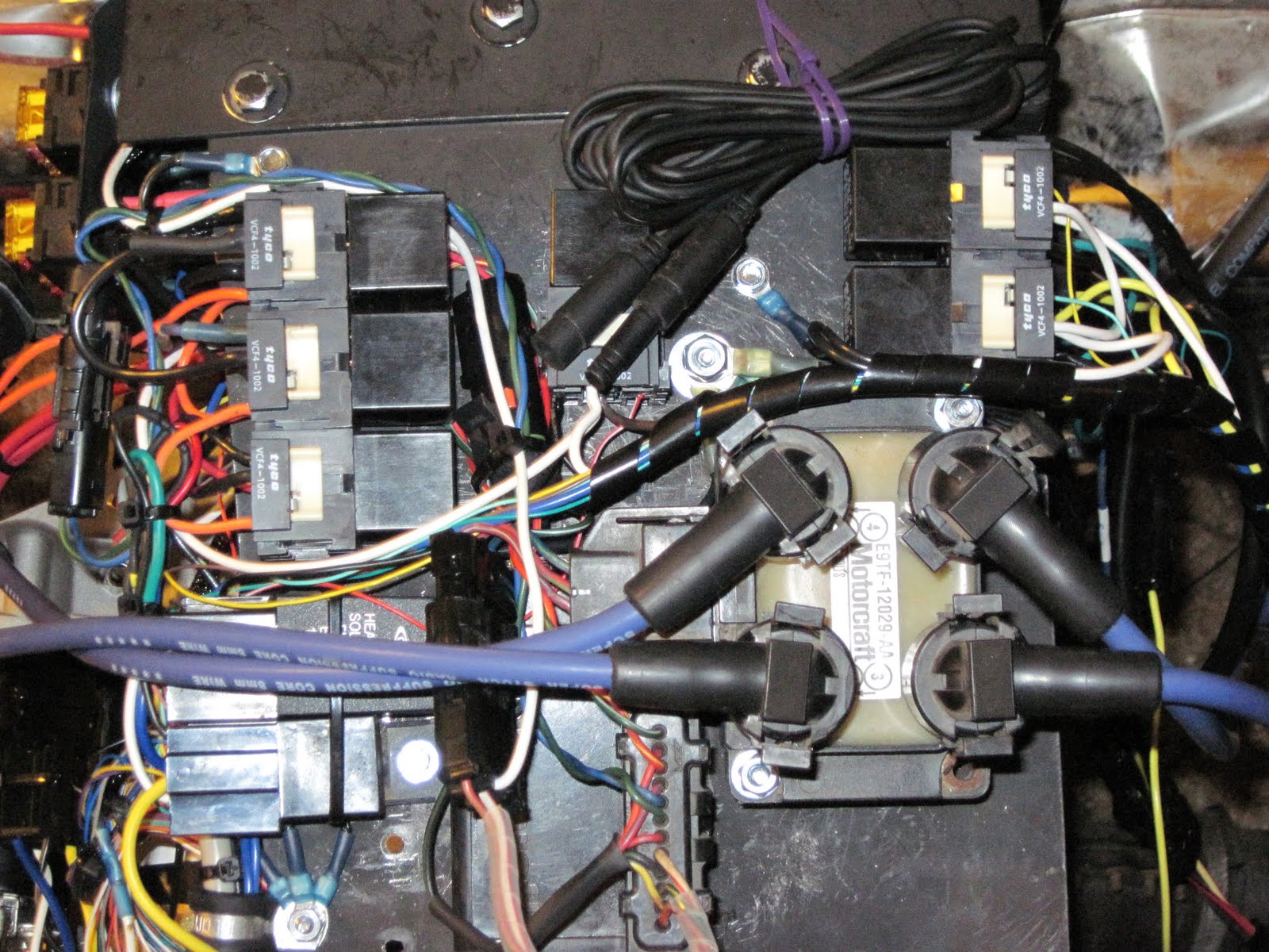
Since I am out of Tyco sockets for the Bosch relays (who'd have thought eight wouldn't be enough?!) I used a relay with a mounting tab and a regular pigtail socket for the horn circuit. Since the pigtail sockets also have a facility for connecting them together, I put the flasher in an adjacent connector and ziptied the flasher to the relay, which is mounted to the plate with the other relays. It looks better than it sounds. All I need now is a horn, hopefully a loud one.
I put wire and connectors on for the body wiring, headlights, taillights, brake lights and turn signals, along with a spare wire that I envision as being for some kind of accessory lighting. I also connectorized the keyswitch, which will also be on the body soon.
I spent a significant amount of time cleaning up the wire routing and putting in zip ties and spiral cable wrap. Some of the wiring cleanup involved making an extension cable or two so that certain wires weren't stretched like guitar strings.
All in all, I have very little chassis wiring left before it's inspection ready. The alternator and N indicators are really optional, as is the tachomter (need some diodes to wire than in) and the speedometer sensor (front wheel; electrically very simple, but I'd like to hide the wiring to it as well as I can; it will be running down the chrome springer front end.
Tomorrow, a couple of mechanical issues and body wiring... Hopefully I won't have to stand and stoop the whole time!
No comments:
Post a Comment