Friday, April 30, 2010

Receiver Hitch

Beginning with this post, I'm going to start displaying most pictures inline rather than with links. I've had a little feedback that indicates that people who look at these updates almost never click on the links, so they don't see the pictures.


Unfortunately, I again neglected to take any pictures until I was finished.

Because of the location of the exhaust, the hitch is a bit to the right of the center line. I don't expect this to be a problem and it was far less complicated that trying to both center it and stay out of the way of the header.


After mocking it up on the bench in several ways, I decided that the easiest would be the simplest, too. I cut a piece of 2" x 1/8" flat mild steel and cut a semicircular hole in one edge. I then ground it to match the profile of the bumper tubing at the angle where it meets.


I sanded all the paint off the contact areas of the receiver tube, clamped the plate in the proper spot and welded the plate to the receiver tube. I then mocked it back up with the bumper and tack welded the flat to the bumper tubing and the back of the receiver tube to the bumper tubing there.

I flipped the bumper over and welded the flat to the bumper tube and as much of the contact area at the back of the receiver tube as possible. This back joint looked too small to me, so I sanded more paint off the bottom of the tube and welded a small flat piece to bridge between the receiver tube and the bumper tube.

I also added a mounting tab for the license plate. By its location, it will also probably hold the interface for the O2 sensor. Sorry for the funky upsidedown pic. No, that is not a small anvil stuck incongruously to the bumper tube. It is actually sitting on the step of the workbench with the face on top, but I wanted the license plate bracket to look "normal".


I dressed and sanded all the joints and it's ready to hand off for powder coating!

Thursday, April 29, 2010

Exhaust and Bumper

I got the chrome stinger and baffle on the way home from work. It seems almost silly to pay $40 for what is essentially a slightly flared pipe with a flange, but I couldn't make one anywhere as quickly as I picked one up. It is the swivel type and bolted on nicely, though I didn't cinch it down permanently. I will need to remove it to drill the stinger and baffle for a retaining bolt. Sadly, this counts as the best picture I took of it. I will take a better one in the daylight and replace it.

I carefully but temporarily placed the bumper to test the clearance with the new O2 sensor bung. It clears nicely!

I dropped the body on to the frame to make sure that it clears the bumper. While it was there, I checked clearance at several other key points, such as the throttle body and air filters, the body mount under the driver seat (which will need about 1/2" of shimming and the nose. I also looked around for open space for mounting the EFI controller. The jury is still out.

With the fit verified, it was time to make the permanent fitting for the bumper. The first step was to bend the upper mounts to coincide with the angle on the shock towers. With my anvil back in place, that was nearly trivial. I would rather have bent them hot, but I was pretty sure my torch is not big enough to heat as large an area as needed.

Of course, one shock bolt was in "backwards", at least for my preferred mounting orientation, but it was easy enough to flip. When the bumper comes back from powder coating and is permanently installed, I will need to switch the bolts out for some that are slightly longer to account for the bumper and the washers it needs to be mounted with. I may even set it up such that loosening the bumper nuts won't affect the shocks. Anyway, I snugged them down tight enough to stay, but loose enough to adjust if needed. I squared and leveled the bumper and made a few measurements to be sure it was as well centered as I could get it and tack welded the bumper to the upper mounts.

The lower mounts will secured with pins so that the bumper can be removed without dropping the transaxle and engine, which I nearly did accidentally with the yellow trike!

I lugged the bumper back to the bench and welded all around the top mounts and dressed the welds in preparation for powder coating. I rounded the corners of the bottom mounts, especially the ends of the tabs that go under the big bolts. I also welded on a license plate mount.

One thing I neglected was to drill a couple of holes in the top tube of the bumper for wiring. They can be drilled after powder coating, but it would probably be a neater job to drill them first.

My plan is to have a 2" receiver hitch on the bumper. The way the stinger fits, it will be nearly impossible to use right away, but I think I will go ahead and put it in anyway, the long term plan being to have a custom exhaust that will clear the hitch. The biggest trailer it should ever be pulling is a small motorcycle cargo trailer, so it doesn't need to be rated for 5000 lbs, but I like the flexibility of the 2" receiver. Besides a tow bar, I can put a cargo tray or a bike rack or even a grill.

Friday, April 23, 2010

Exhaust. Again. Or More... Whatever...

As I suggested before, I tried to heat the area around the O2 sensor bung so as to adjust the angle at which the sensor sits, due to it's interference with the bumper. My little torch can't heat enough area to make that strategy viable, so I decided to go with plan B, which was to plug that fitting and install a new one on the other side of the collector.

Well...

I suspect that some steel shot from the Wheelabrator must have gotten in the threads of the sparkplug, which was ironically there to protect the threads, from inside the collector. It turned about one quarter turn and seized firmly. Ratchet, breakover, 2 foot cheater and hammer impact wrench couldn't touch it. I spent nearly an hour struggling with it before I adopted a new plan C and took it to the BTW clubhouse to use the *real* torch to cut the fitting out.

I brought it back home and welded in an actual official O2 sensor bung, as opposed to the chopped off spark plug anti-fouling device used before. Even though the torched out hole was significantly too large, I did a somewhat better job putting this one in. I think I even got the angle right. I did have to use a bit of 3/16 rod as filler around one side of the bung. Oh, and here's a tip: don't poke yourself in the neck with red hot metal.

I spent a bit of time chipping  and sanding off sputter and generally cleaning up the joint. I then degreased the header and sprayed on a coat of paint. I will let that dry overnight, then flip it over and paint the other side.

So, basically I spent an entire evening working on one little thing. Ugh.

Headlight

The HID conversion kit arrived earlier this week and the halogen reflector arrived today. I verified that the parts fit together and assembled them into the existing headlight bucket. It looks pretty good. Looks even better installed.

Thursday, April 22, 2010

Jinx?

I probably shouldn't say anything, but it looks likely that I may get to work on the trike tonight!

The trigger wheel is possibly going to be shipped tomorrow.

My H4 to HID conversion kit arrived yesterday and the H4 headlight arrived today!

Wednesday, April 21, 2010

HID Converter arrives; Upholstery in the works

While the sealed beam headlight is probably adequate for the Dragon Trike, I decided that I would like to update it. Its a pretty standard 5 3/4" headlight, probably salvaged from a current model Sportster when the trike was built in the mid-70's. There are lots of kits to convert sealed beam to halogen, notably using the H4 bulb.

There are also kits to convert halogen lights to HID.

So, I have ordered both. I have a halogen replacement headlight coming and today I received the HID kit to convert the new headlight.

The little 12 volt supply at my desk doesn't provide enough current to light it effectively, so I'll have to play with it later....

 I spoke with an upholsterer of some renown. Looks like it will run about $350. He has some cool snake/lizard pattern vinyl that seems appropriate for a dragon trike....

Monday, April 19, 2010

Dragon Trike Bumper and Exhaust Stuff

I have been trying to keep subjects that are EFI specific on the EFI page and other work here. For a long time, little was done on the Dragon trike that wasn't directly related to the EFI project, so posting has been sparse over here. Well, that's changing. There is still PLENTY to do on the engine, but in order to have something to be riden the engine is running, I need to get crackin' on the rest of the project.

By far, the biggest must-do is wiring. When I acquired the trike, it had just enough wiring to start and run the engine. It did not even charge the battery. There was a toggle switch and a push button mounted on a little rectangle of wood, secured to a screwhole in the left cooling tin. All the basic engine wiring was there, battery, distributor, ballast resistor, ignition coil, anti-runon solenoid, electric choke and starter. The alternator worked but was not connected to charge the battery. I had, in fact, taken it around the neighborhood where, once killing the engine with bad clutching I had to pull over, make sure it was in neutral but not rolling, get off, run around back, restart the engine, get back on and ride off.

I digress.

I'm picky about the wiring and I want a few nice features, so it will be a fairly extensive project, but it will be reliable and easy to troubleshoot. Easy to troubleshoot is important because I have DIY electronic fuel injection, an electronic gauge that includes speedometer, tachometer, fuel level and several indicator lights, a switch pod with turn signals, hi and low headlights, starter and horn and lighting will include headlights, marker lights, turn signals, driving lights and backup lights, not to mention that some kind of effects lighting will probably be done, too. Phasers and photon torpedoes will be in phase III.

All of this stuff will be wired with an eye toward computer controlling the whole thing someday.

Besides wiring, I need to make a couple of minor adjustments to properly fit the body to the frame (which will probably affect how the shifter mounts), a footrest for the short term and a floorboard for the long term and while the front wheel is kinda serviceable, I don't really trust it for any kind of long trip.

In Texas, there is some confusion as to whether one needs brakes on all wheels. Texas Transportation Code, Chapter 547, indicates that front brakes are not required if braking performance meets certain criteria, which are pretty accessible to all the rear-brake only trikes I've seen. The annual inspection procedure, however, seem to require brakes on all wheels with no allowance for exceptions, at least none that I have found. I am not a lawyer; I do not play one on TV.

It needs upholstery of some sort and I have the baja bumper to mount.

Oh, yeah, the title of this post is "Dragon Trike Bumper and Exhaust Stuff"... betcha thought I forgot about that....

Long story short, I had my exhaust system and while I was waiting for the bumper to arrive, I welded in a bung for the O2 sensor and had the system shot peened to remove the crappy factory paint. While the bumper arrived a few days before, it was Saturday before I got to mock it up to see how it was going to fit. Then I put the exhaust header on and found that  the bumper and the exhaust interfere in two places.

First thing I noticed is that the O2 sensor hits the bumper. There are a couple of ways to get around that. I think I will try heating the area around the bung and bending to make it sit parallel to the ground. If that doesn't look like it will work, I can just plug that fitting and put in another, probably on the opposite side.

The other thing is that the muffler supplied with the header is made for a sedan and the bumper is not. The easiest solution is to ditch the muffler (probably too quiet, anyway) and bolt on something else, most likely a stinger.

The muffler and O2 sensor 
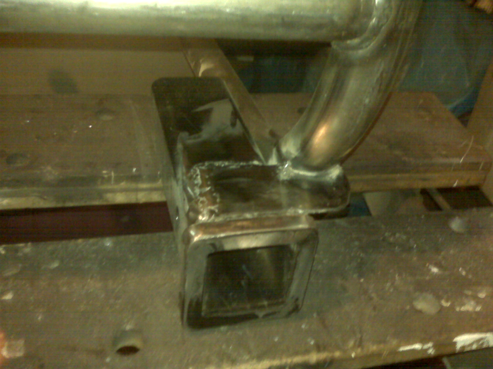
placement will also affect the placement of the planned receiver hitch. I have a 2" receiver hitch tube ready to weld to something, probably the bumper. I thought about putting a ball on a plate, as it often done for trikes, but the 2" receiver hitch leaves a lot of options. It's not like I'll be pulling around an RV, but being able to put on a ball, or a cargo rack or even a bike rack, not to mention more lighting, is appealing. If things go according to my current theories, the hitch tube will go a bit right of center on the bumper.

Woah! An update!

I have spent most of my trike time working on the engine of the Dragon Trike, specifically the conversion to EFI. You can see details here.

Since the speedometer was installed on and subsequently became usable, the Yellow Trike has accumulated nearly 2000 miles. It has been on a couple of road trips, generally 200 mile per day excursions. It has been pretty reliable, though not without the occasional bobble, just nothing to stop the trike.

Well, except I need to keep a close eye on the fuel level. Not the trike's fault if I run it dry.

More importantly, the Dragon Trike is well underway, with a deadline to have it driveable by Memorial Day weekend. As of this writing, that is essentially 45 calendar days.

Followers