Between day job and copious paint prep work, I haven't had much time to update the blog. This evening, however, we reached a forced stopping point and I thought I would pound out a few verbs and nouns.
The nature of paint prep work appears to be that for every task completed, 1.6 tasks replace it. At some point, ya gotta say "enough" and get some color on the thing.
Before reaching that point....
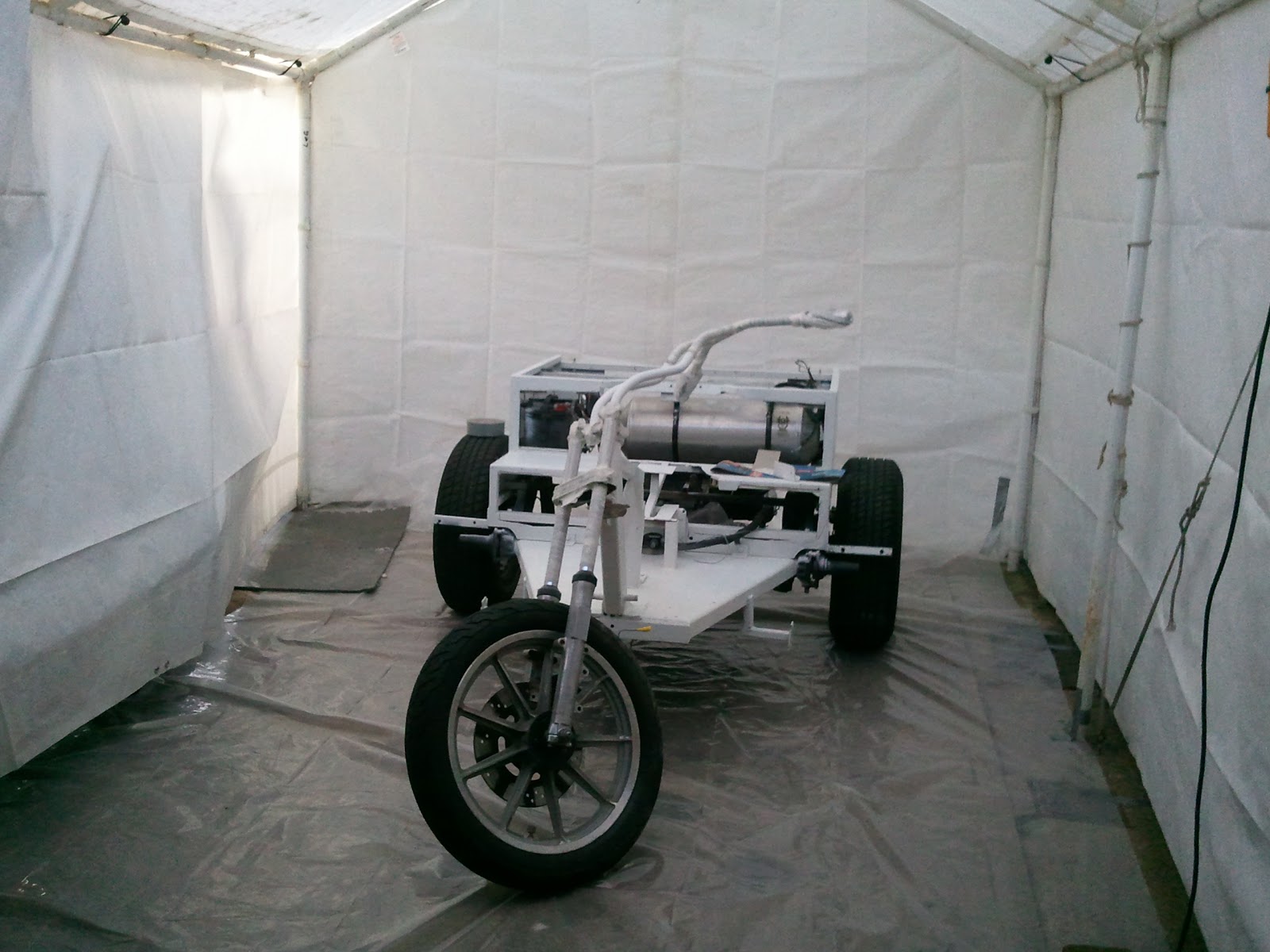
May I present the newest material for forks, masking tape. Good thing it's there, too, because the process revealed that the bearings need to be replaced. It's always something...
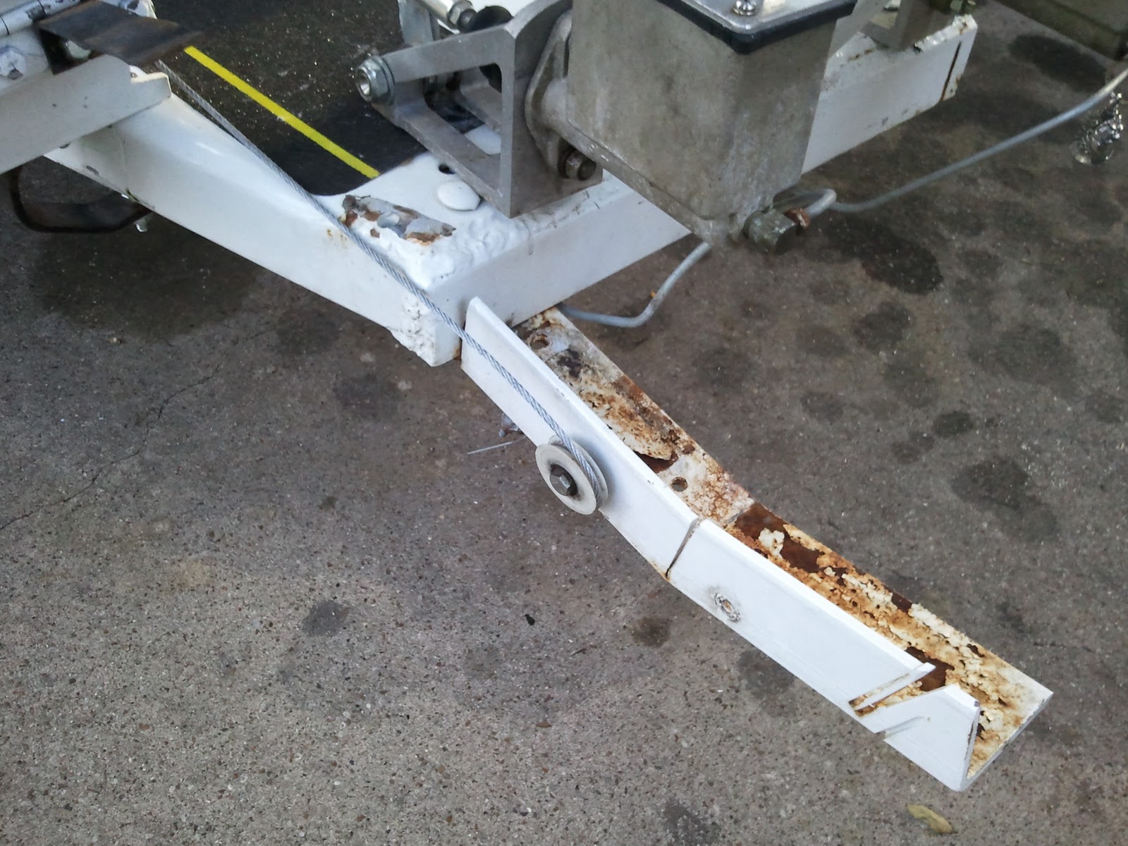
The step fric stuff came off pretty easily, though not quite as easily as this picture might have you believe. We found new ones just like them at Home Depot, so we'll be able to put some back.
The dreaded metal mites. Only 4 of these holes are currently useful.
Sadly, I can't count under the influence of Bondo fumes.
Gabby stained the wood that will go over the openings left by the removal of all that expanded metal.
She also repainted the engine with a plain silver. The other stuff was just too blue.
I broke the foot pegs and accelerator pedals down as far as I could without cutting metal. I cleaned them up as best as I could with the grinder, wire wheel, sander, etc. Even drilled out the drain holes that had been blocked by sloppy welding.
The inside of the fenders got a coat of cheap black enamel that was sitting around in the garage.
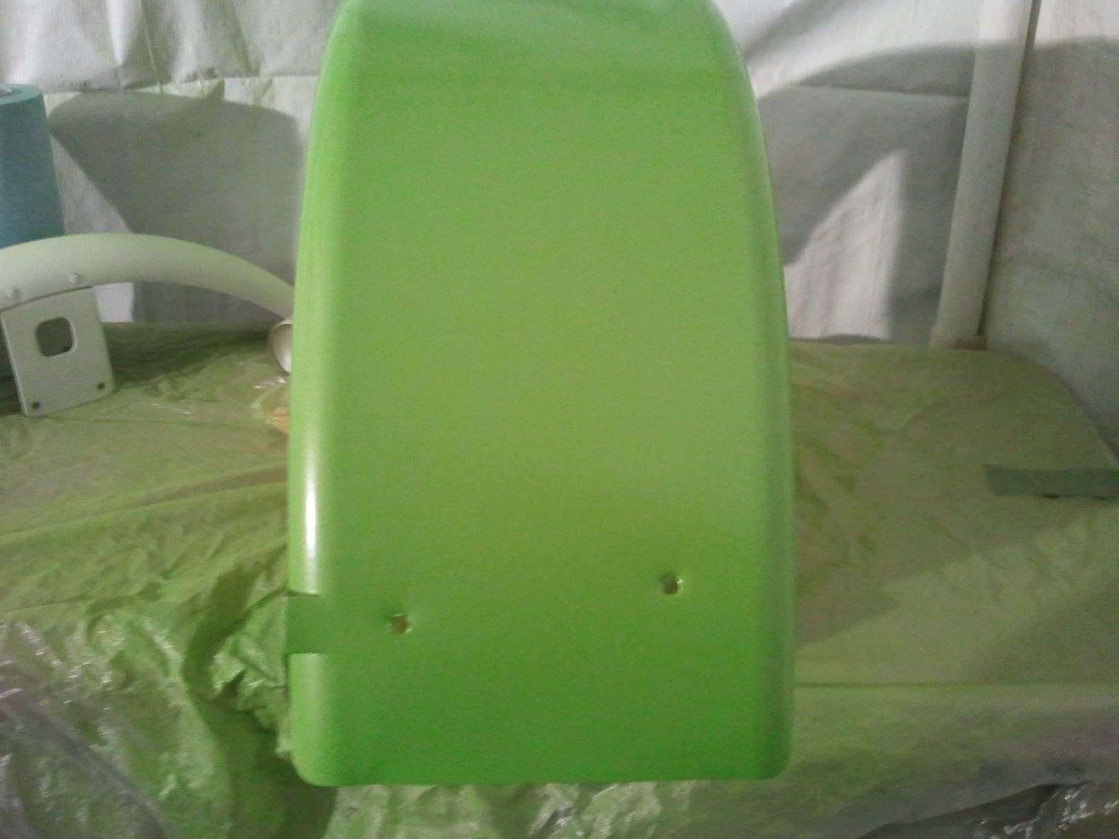
The fenders got a coat of primer. There are two rear fenders. It pretty much take a full rattle can of primer for the two. I think we've been through at least 5 cans of primer.
I neglected to take pictures of it, but the old shifter shaft was spliced with a piece of 1/2" EMT and two 1/4 x 20 bolts. I was able to get it settle down by cranking the bolts down, but the way it was put together, it just wasn't stable.
In the interest of spending the least time one it, but still fixing it, I took it apart, wire brushed all the galvanizing off the splicer bit and worked the original VW parts back into round. I put the bolts through the holes, just as temporary pins, and clamped the assembly to the inside of a big piece of angle iron to keep it all straight. Did a couple of tack welds then welded both ends all the way around. I dressed the welds with the grinder, a file and the wire wheel and it's ready to install.
So we could paint the sides unimpeded, we pulled the wheels off. The big square notch was added, apparently to allow clearance for the brake caliper.
Here is most of my redneck paint booth. The 10 x 20 garage tent, with walls, has served as a permanent carport extension for several years. Add the walls, a drop cloth and voile! Paint booth!
I'm a new believer in cartridge respirators. I pulled it off inside the booth immediately after the first cup ran out. Much to my surprise, while painting, you simply cannot smell paint, even if it is knockdown strength without the respirator. I will endeavor to use one from now on. This one was $15 at Harbor Frieght.
Finally.... There's color on the trike!
This took two cans of the paint and our nearby stores that had it in stock were closed, so we were stopped for the night.
What's left to paint is the other fenders, the trunk, the deck lids, the "tank" dashboard thing, the bumper, the cooling tins and a few miscellaneous small parts.
Oh, and assembling it. It's pretty much dismantled at this point.
Wednesday, September 28, 2011
Sunday, September 25, 2011
More Paint Prep
During the work week, I didn't have a lot of opportunity to work on the trike, though I did get some done. Friday night and Saturday is when I got to spend a lot of time on it.
While riding *last* weekend, I noticed a small fresh looking pool of brake fluid under the trike after we stopped for fuel. There were no obvious leaks, so we decided to let it go for the moment. During the week, I noticed two things that I think may have been related.
The fuel tank petcock was very close to the clutch slave cylinder, specifically the boot around the shaft..
This pic was taken later and doesn't show that the fuel line was dripping liquid, which turned out to be brake fluid from the cylinder. If you look closely, it does show signs of a leak in the area.
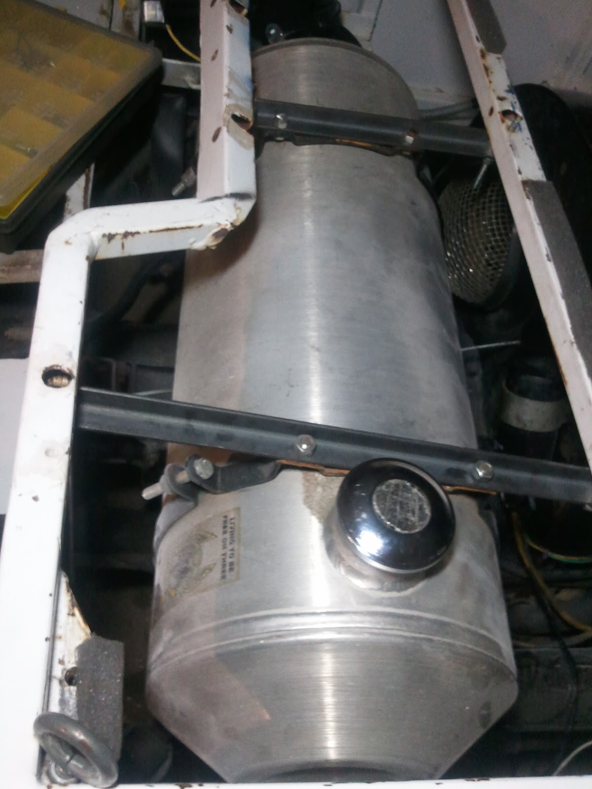
The fuel tank mounting needed to be redone regardless. The brackets it was hanging from were made from flat stock. The weight of the tank, about 50 pounds full, is more than they could take over time.
Note also that the nut one would expect to find on the bolt in the foreground was missing already.
Though it's hard to see in this picture, the left backet is actually curved.
I used a load strap to temporarily support the tank while I removed the old brackets and rebuild them from angle stock. Even with their optimistic choice of flat material, the previous builder apparently did understand the need to offset the holes. Especially with the longer brace, the brace is mounted at a slight angle to the center line of the trike and the tank, while sadly not quite perpendicular to the center line, it it mostly perpendicular. These factors combine to mean that the four holes drilled in the bracket are not along the center line of the bracket. It was easiest to use the old ones as a templates (after flattening them on the anvil) and drill the same relative positions in the new ones.
I think the original trike did not have the relief in the frame for the passenger seat. There is ample evidence that this was cut in and redone. To get the angle more seat-friendly, the center section was angled to the ground. Unfortunately, the front fuel tank mount is on that piece and the angle on the frame piece not only essentially lowers that point by about one inch, but places it at an angle as well. In a more perfect world, I would take time to correct this, and it might be as simple as heating and bending the mounting tab back to level with the ground. This would be enough to get it all the way back to the right height, but it would help. For now, I am just using as it is, which meant having quite a bit of difficulty getting that bolt to line up properly. Alas, I won in the end.
Even with the new rigid brackets in place, this frame issue makes the tank sit not quite level.
It will not be visible once we're done, but it will leave a small bit of fuel inaccessible when it runs very low and it may result in sediment collecting in the tank rather than flowing out and being caught in the filter. Which, by the way, I will have to add. Perhaps most importantly, the tank clears the newly replaced clutch cylinder by a better margin.
The clutch cylinder also got a new bracket that allows it to pull against the transaxle. The old one pulled against the trike frame, which is not a great idea for smooth clutch operation.
One thing I kept in mind while remounting the tank was the position of the filler in the existing (rather ugly) fuel door.
We are keeping this deck material for time being, so we want this thing to look as good as it can. We are using a Bully billet fuel door intended for GM pickups. It has the least extraneous hardware on the back of it, compared to models for Ford and Dodge trucks. :)
I had to line the door up carefully to center the filler cap beneath it and to maximize on holes that would actually be drilled in the deck. I also had to cut out a little bit towards the back of the trike to clear the stop that door rests on when closed. All done, the fuel door looks GREAT and I can only imagine how much better it will look after the deck is painted.
The fuel door is most assuredly the shiniest bit on the trike.
Saturday was a good long workday. I started by rolling the trike out in the driveway and powerwashing everything I could reach, especially on the engine. I used my yard blower to speed dry every nook and cranny, then I remember that I had intended to wet sand all the surfaces. So, that was about an hour and some spots will need touch up sanding, but for the most part it's sanded and it must be extra dry since I had to use the blower a second time :)
Next came the dismantling.
I started with the engine because I knew we'd want all those parts off the trike for their own beautification.
The engine being smaller with all the stuff off it will be easier to mask when we paint the body. With the tins off, I discovered several cooling issues.
First, and not surprisingly, there were mud dauber nests all over fins on the cylinders. I'm not sure what the attraction is to such spots, but it is a common occurrence, especially when one sits unmoved for a long time as this one did.
Also visible in this picture is the infamous under shroud oil cooler that is known for cooling the oil pretty well by stealing the air needed to cool cylinder #3. This will need to be corrected soon, but not this week.
You can't see it in any of the pictures I took, but on the 1-2 side, there was something soft and fluffy, maybe fiberglass, blocking the same center air passage as the mud daubers blocked on 3-4. It was drenched in oil and dirt from some years of operation, so it's not new. I theorize that, at some time in the engine's past, a mouse lived there.
I degreased as best I could with spray chemicals and brushing. What a mess that was, and I'm not truly happy with the results, but I'm on such a tight time budget for this project. Some things just have to wait.
I did mask and shoot the engine block with a coat of paint. The paint looks way more blue than the cap looked in the store. The cap matches it perfectly now, but still, more blue than expected.
I also painted the unremovable pulley, speaking of a project to put off...
I removed the rear bumper, the lights and the little stainless steel plate that I think was originally intended as a place for the inspection sticker, and the wiring harness from the back of the trike.
I ground and sanded the welding bumps left from the expanded metal that had been on the right side of the trike.
That was a mess.
Also removed the extremely ugly bracket that first held the brake pedal (which we moved onto the floor deck a week ago) but cannot yet be eliminated because of the throttle cable routing. Yet another project to delay.
I severely shortened it and rounded all the edges that are exposed and shot it with primer.
I removed the clips holding the wiring harness between the back of the trike and the fuse panel and the entire shifter assembly. I shot some scratched and scraped spots with primer and will need to sand and prime a few more places, as well as wet sand a few previously inaccessible areas.
Finally, I installed a blind nut rivet for one of the "fuel tank" dashboard mounting tabs. It had a bolt simply jammed in the hole before, or at least if there was a nut, it's completely inaccessible now. This was my first try at this fastener and I must admit, I'm impressed. I nabbed this picture of one installed from the web.
I don't think I'd hang the transaxle from one, but it works really well for this application.
Today, more prep and, hope upon hope, shooting some paint...
The Paintman Cometh
We spent much of Sunday shopping for stuff more or less directly connected with painting the soon to be formerly white trike.
The right fender was slightly damaged in what is reported to be an accelerator mishap. It had been pounded back into shape reasonably well, but we wanted to replace it before painting. that sort of thing always shows through.
Northern Tool had fenders that were pretty close, so we got two so we can replace both to match. As a bonus, there is probably enough good fender on both of the old ones to redo the fenders on Sponge Bob.
It looks like the old fenders on the trike were previously on another trike and the mounts on the trike look like they were originally made for other fenders. [This is the fourth version of that sentence, and I still don't like it]
I started with the banged up fender.
The new fenders are slightly smaller, so I removed a bracket "extender" of sorts (just visible at the rear of the fender above) and it looks like the original brackets will fit them. I then measured and cut a notch in the front of the fender to clear the mount. Once the notch fit well, I marked the back of the fender and cut that notch. That fender appears to fit perfectly. Then I repeated for the other fender. Somehow, I manged to avoid photographing the new fenders.
The right fender was slightly damaged in what is reported to be an accelerator mishap. It had been pounded back into shape reasonably well, but we wanted to replace it before painting. that sort of thing always shows through.
Northern Tool had fenders that were pretty close, so we got two so we can replace both to match. As a bonus, there is probably enough good fender on both of the old ones to redo the fenders on Sponge Bob.
It looks like the old fenders on the trike were previously on another trike and the mounts on the trike look like they were originally made for other fenders. [This is the fourth version of that sentence, and I still don't like it]
I started with the banged up fender.
The new fenders are slightly smaller, so I removed a bracket "extender" of sorts (just visible at the rear of the fender above) and it looks like the original brackets will fit them. I then measured and cut a notch in the front of the fender to clear the mount. Once the notch fit well, I marked the back of the fender and cut that notch. That fender appears to fit perfectly. Then I repeated for the other fender. Somehow, I manged to avoid photographing the new fenders.
Thursday, September 15, 2011
Bit O' Tinkerin'
I versed the turn signals on the white trike... re-reversed, I guess. I figure two re's make a null, so "versed". In any case, they work as expected now... :)
One of the troubles with this trike is the sloppiness of the shifter. It's a fairly short linkage, but when we got it, there was obvious movement in every single piece. The shifter itself was sloppy and missing the tension spring. The shifter box is only bolted on the front end, leaving the back end able to lift and move, especially when shifting to 1st or 3rd. The shaft had been spliced with a piece of 1/2" EMT with a single 1/4" bolt through each half, and those were lose. The coupler to the transaxle is a little worn. I presume the hockey stick bushing is sloppy, though I haven't specifically investigated that.
Really, improving any one of these areas would be enough to help, and indeed, just tightening the two 1/4" bolts splicing the shaft together helped. Installing a new standard Empi shifter and greasing the internals in the shift box helped even more, and restored proper reverse lockout operation.
There was an unused, or perhaps more precisely, abandoned, bolt hole in one corner of the shifter box. It went through the top of the box, the bottom of the box, the deck and through the 2" square tubing beneath that. The very bottom hole and the rest of the holes did not quite line up, but by the simple expedient of putting a slight bend in the bottom 1" or so of a piece of all thread, I was able to fish it through. I cut it to length and tightened down. It eliminated all but the slightest detectible movement of the shifter box and shifting improved about 10 times.
In exercising it, however, I noticed it was much stiffer shifting into 2nd, 4th and reverse that to 1st and 3rd. Watching that action while running through the gears revealed that the short end of the shaft flexes enough when going to the even gears that it puts the shaft in a bind within the bushing at the rear of the shift box. I found that I could loosen the new bolt and actually improve operation minimally. What turned out to work better was lubricate the bushing. I couldn't find my grease gun, so I used silicone spray for the short term and it served as the miracle cure.
The real solution will be to stabilize the shaft then maybe to adjust the height of the shifter box and/or the bushing if needed.
I think I can take this shaft out and either weld it into one piece or replace it with a newly fabricated one and eliminate almost all these issues.
The last thing I did was cut a new gasket for the front brake master cylinder. It apparently drips when underway, resulting in brake fluid drops on the right shoulder. Maybe good for street cred, but little else. For the ride home last night, we just tied a rag around it. :)
One of the troubles with this trike is the sloppiness of the shifter. It's a fairly short linkage, but when we got it, there was obvious movement in every single piece. The shifter itself was sloppy and missing the tension spring. The shifter box is only bolted on the front end, leaving the back end able to lift and move, especially when shifting to 1st or 3rd. The shaft had been spliced with a piece of 1/2" EMT with a single 1/4" bolt through each half, and those were lose. The coupler to the transaxle is a little worn. I presume the hockey stick bushing is sloppy, though I haven't specifically investigated that.
Really, improving any one of these areas would be enough to help, and indeed, just tightening the two 1/4" bolts splicing the shaft together helped. Installing a new standard Empi shifter and greasing the internals in the shift box helped even more, and restored proper reverse lockout operation.
There was an unused, or perhaps more precisely, abandoned, bolt hole in one corner of the shifter box. It went through the top of the box, the bottom of the box, the deck and through the 2" square tubing beneath that. The very bottom hole and the rest of the holes did not quite line up, but by the simple expedient of putting a slight bend in the bottom 1" or so of a piece of all thread, I was able to fish it through. I cut it to length and tightened down. It eliminated all but the slightest detectible movement of the shifter box and shifting improved about 10 times.
In exercising it, however, I noticed it was much stiffer shifting into 2nd, 4th and reverse that to 1st and 3rd. Watching that action while running through the gears revealed that the short end of the shaft flexes enough when going to the even gears that it puts the shaft in a bind within the bushing at the rear of the shift box. I found that I could loosen the new bolt and actually improve operation minimally. What turned out to work better was lubricate the bushing. I couldn't find my grease gun, so I used silicone spray for the short term and it served as the miracle cure.
The real solution will be to stabilize the shaft then maybe to adjust the height of the shifter box and/or the bushing if needed.
I think I can take this shaft out and either weld it into one piece or replace it with a newly fabricated one and eliminate almost all these issues.
The last thing I did was cut a new gasket for the front brake master cylinder. It apparently drips when underway, resulting in brake fluid drops on the right shoulder. Maybe good for street cred, but little else. For the ride home last night, we just tied a rag around it. :)
Puff Shifter
Since Gabby took the white trike to work tonight, I reworked the shifter on Puff.
The first thing I did was shop for a ratchet U-joint with the least play in it. I chose a spark plug socket with a built in U-joint. here it is compared to the previous joint for the transaxle end.
First, I cut the end off the other joint. It is part of an adjuster, so it is the proper size for the coupler and includes a set screw dimple. I also cut the end of the socket off so that when the end is bottomed into it, it is the minimum length. This should make the entire assembly shorter with less side loading when shifting.
I clamped it up...
And welded it together.
I then cold forged the the end of the tube to fit the drive end of the socket and welded that. There is the completed joint.
I test fit the shaft to get an idea where I would have to move the shifter.
Next came the tougher bit. I repositioned the Super Shifter so that the new shaft can be used with it's single U-joint. First, I cut off my ever-so-carefully placed shifter mount, then cut the rear bracket shorter, while hand fitting the shifter. Once I was "happy" with the placement, I used a jack to hold it at the right height, a drill bit under the box to hold it at the correct angle to the ground and a C-clamp to clamp it to the shaft for the proper angle to the transaxle.
Sorry about the odd angle. I was trying to eliminate shadows and reflections off the chrome box. I ended up leaning so far over that it's like I held the camera upside down.
Anyway, made those two welds and I really hope the fiberglass body still matches up correctly.
All that remained was to cut the shaft to length and to grind the end down to fit in the coupler.
I have used a drill bit as a temporary pin, but here's the completed shifter.
Compare the angle with the previous attempt:
This layout works MUCH better. It works so well that I foresee speedshifts.
The first thing I did was shop for a ratchet U-joint with the least play in it. I chose a spark plug socket with a built in U-joint. here it is compared to the previous joint for the transaxle end.
First, I cut the end off the other joint. It is part of an adjuster, so it is the proper size for the coupler and includes a set screw dimple. I also cut the end of the socket off so that when the end is bottomed into it, it is the minimum length. This should make the entire assembly shorter with less side loading when shifting.
I clamped it up...
And welded it together.
I then cold forged the the end of the tube to fit the drive end of the socket and welded that. There is the completed joint.
I test fit the shaft to get an idea where I would have to move the shifter.
Next came the tougher bit. I repositioned the Super Shifter so that the new shaft can be used with it's single U-joint. First, I cut off my ever-so-carefully placed shifter mount, then cut the rear bracket shorter, while hand fitting the shifter. Once I was "happy" with the placement, I used a jack to hold it at the right height, a drill bit under the box to hold it at the correct angle to the ground and a C-clamp to clamp it to the shaft for the proper angle to the transaxle.
Sorry about the odd angle. I was trying to eliminate shadows and reflections off the chrome box. I ended up leaning so far over that it's like I held the camera upside down.
Anyway, made those two welds and I really hope the fiberglass body still matches up correctly.
All that remained was to cut the shaft to length and to grind the end down to fit in the coupler.
I have used a drill bit as a temporary pin, but here's the completed shifter.
Compare the angle with the previous attempt:
This layout works MUCH better. It works so well that I foresee speedshifts.
Wednesday, September 14, 2011
A Thousand Points of Light
Ok, maybe not a thousand...
Gabby was running late enough that she didn't take the white trike to work on Tuesday night, so I put the handlebar switch on and wired it up.
Because the new headlight has a halogen bulb and I wanted to put the auxiliary light on with the high beam, I used a relay to power the headlights rather than smoke the old motorcycle switch. Fused power is on the common (30) and one side of the coil (85), low beam on the normally closed (87a) and high beam/auxiliary on the normally open (87). The high beam position of the switch grounds the other side of the relay coil (86)
I also connected the horn button and the turn signals. I did not, however, test the signals and managed to reverse them! Left switch signals for a right turn and vice versa. It's taped and tied down well enough that I didn't want to tear it open to swap them. I ran out of time, but I should have it again Thursday night and I'll swap them back to normal then.
Gabby was running late enough that she didn't take the white trike to work on Tuesday night, so I put the handlebar switch on and wired it up.
Because the new headlight has a halogen bulb and I wanted to put the auxiliary light on with the high beam, I used a relay to power the headlights rather than smoke the old motorcycle switch. Fused power is on the common (30) and one side of the coil (85), low beam on the normally closed (87a) and high beam/auxiliary on the normally open (87). The high beam position of the switch grounds the other side of the relay coil (86)
I also connected the horn button and the turn signals. I did not, however, test the signals and managed to reverse them! Left switch signals for a right turn and vice versa. It's taped and tied down well enough that I didn't want to tear it open to swap them. I ran out of time, but I should have it again Thursday night and I'll swap them back to normal then.
A Little Light Drama
No light is dramatic at night.
After the BTW meeting, Gabby rode the white thing to work, with me and Sponge Bob in escort. There were no (known) problems. When she got off work that night, she had no main headlight and the smaller "high beam" was dim and/or flickering. I did some quick field testing and decided that the bulb must have gone, as new stuff is sometimes likely to do. We used some wire ties and spit to get the smaller light to stay on and rode on home.
This evening, I chased down the troubles, and there were indeed two independent failures. Some NASA engineer is getting fired for this...
First, the main headlight, the new one. I'm the engineer getting canned for that one. I used a self-soldering heat shrink type of connector and maybe I didn't heat it enough or something. It didn't bond well and with it sinking current for two halogen filaments simultaneously, it heated up and came unsoldered. Ground open, no light.
The smaller high beam thing had a similar problem, but this one wasn't my fault. This light was operated by a small rocker switch mounted on a bracket on the left mirror bracket. Neither the wire nor the solder point on the rocker switch was adequate to power that light. One of the wires had come unsoldered from a switch terminal. The wire can't be any bigger than 20ga and the switch is probably good for 1A. For the short term, I connected the lead from the light directly to power in it's harness.
So, the white thing's headlights are semi-permanently wired to the keyswitch.
I have begun refurbishing the handle bar switches (and throttle) from a Suzuki something or other than the previous owner of Puff threw in. They fit one inch bars. I wire brushed all the paint and corrosion off the left one and painted it. I decoded the wiring and I will be ready to install it one evening this week. It will cover hi/lo, turn and horn. The right hand switch has a run/stop switch and a start button. Just this moment, those functions are covered elsewhere, but I'll still be interested in using them.
Tinker gave me a couple of screws for the cooling tins. I applied them both the cylinder tins. The 1-2 cylinder tin didn't have any screws at all. Neither did the doghouse.
Then I noticed a bigger problem. The righthand fuel tank bracket either lost it's bolt or never had one. There is a welded-on 3/8" nut on the frame bracket it bolts to and it had a lot of rust inside.
Anyway, I found 5/16" bolt and nut, manhandled the full 8 gallon tank into position and bolted it down. Someday, I will replace the 1/4" x 1" flat straps with 1" angle or maybe 1" square tubing. Either would be way more rigid and better suited to holding up 48 pounds of gasoline.
After the BTW meeting, Gabby rode the white thing to work, with me and Sponge Bob in escort. There were no (known) problems. When she got off work that night, she had no main headlight and the smaller "high beam" was dim and/or flickering. I did some quick field testing and decided that the bulb must have gone, as new stuff is sometimes likely to do. We used some wire ties and spit to get the smaller light to stay on and rode on home.
This evening, I chased down the troubles, and there were indeed two independent failures. Some NASA engineer is getting fired for this...
First, the main headlight, the new one. I'm the engineer getting canned for that one. I used a self-soldering heat shrink type of connector and maybe I didn't heat it enough or something. It didn't bond well and with it sinking current for two halogen filaments simultaneously, it heated up and came unsoldered. Ground open, no light.
The smaller high beam thing had a similar problem, but this one wasn't my fault. This light was operated by a small rocker switch mounted on a bracket on the left mirror bracket. Neither the wire nor the solder point on the rocker switch was adequate to power that light. One of the wires had come unsoldered from a switch terminal. The wire can't be any bigger than 20ga and the switch is probably good for 1A. For the short term, I connected the lead from the light directly to power in it's harness.
So, the white thing's headlights are semi-permanently wired to the keyswitch.
I have begun refurbishing the handle bar switches (and throttle) from a Suzuki something or other than the previous owner of Puff threw in. They fit one inch bars. I wire brushed all the paint and corrosion off the left one and painted it. I decoded the wiring and I will be ready to install it one evening this week. It will cover hi/lo, turn and horn. The right hand switch has a run/stop switch and a start button. Just this moment, those functions are covered elsewhere, but I'll still be interested in using them.
Tinker gave me a couple of screws for the cooling tins. I applied them both the cylinder tins. The 1-2 cylinder tin didn't have any screws at all. Neither did the doghouse.
Then I noticed a bigger problem. The righthand fuel tank bracket either lost it's bolt or never had one. There is a welded-on 3/8" nut on the frame bracket it bolts to and it had a lot of rust inside.
Anyway, I found 5/16" bolt and nut, manhandled the full 8 gallon tank into position and bolted it down. Someday, I will replace the 1/4" x 1" flat straps with 1" angle or maybe 1" square tubing. Either would be way more rigid and better suited to holding up 48 pounds of gasoline.
Subscribe to:
Posts (Atom)