Wednesday, May 26, 2010

My Feet Are Tired!

After setting out some grass in the front yard and doing so overdue pool maintenance, I got to wiring. By midnight, I had reached a hard stopping point, though slightly short of my goal. I had wanted to have *all* chassis wiring done, but I am short a horn, need to do some ECU programming before I hook up the N light and I need something to make the alternator light work right.

A Volkwagen alternator needs a filament bulb to make the built in voltage regulator work right, so you can't just put an LED on it. I have a generic indicator light that I have been using. It's pretty common to put an LED indicator in parallel and put the LED on the dash. However, the voltage that lights the light is low enough that it wont light the LED on my speedometer. I will need to investigate, but in the mean time, I will put in a temporary switched 12V lead to my generic indicator because it won't charge without the bulb in place.

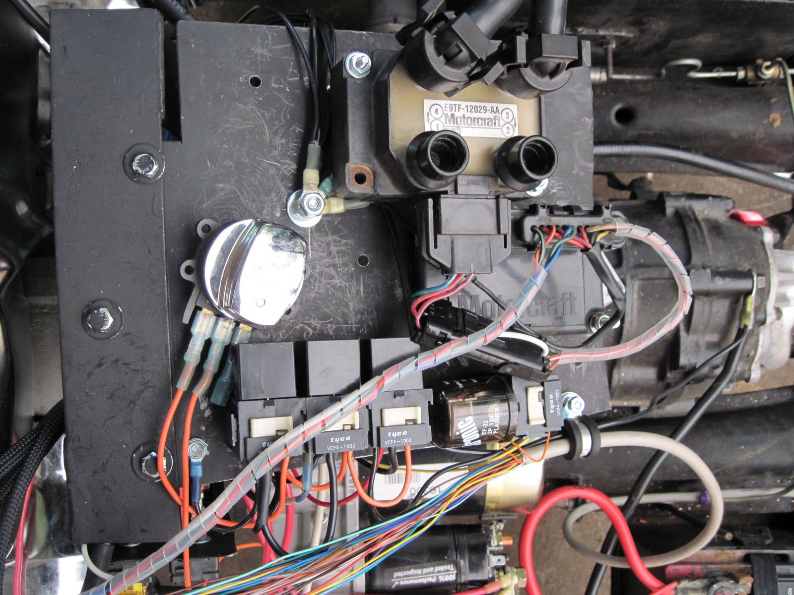
I replaced the "standard" electronic flash that I had with a flasher made for LEDs. Where the other flasher needs a load of about 1A to flash correctly, this one is rated for 20mA to 25A. It works perfectly with the relays. In this setup, the relays and the LED turn indicators on the speedo are the only load on the flasher. It drives a relay and the lights are driven from the relay.

Since I am out of Tyco sockets for the Bosch relays (who'd have thought eight wouldn't be enough?!)  I used a relay with a mounting tab and a regular pigtail socket for the horn circuit. Since the pigtail sockets also have a facility for connecting them together, I put the flasher in an adjacent connector and ziptied the flasher to the relay, which is mounted to the plate with the other relays. It looks better than it sounds. All I need now is a horn, hopefully a loud one.

I put wire and connectors on for the body wiring, headlights, taillights, brake lights and turn signals, along with a spare wire that I envision as being for some kind of accessory lighting. I also connectorized the keyswitch, which will also be on the body soon.

I spent a significant amount of time cleaning up the wire routing and putting in zip ties and spiral cable wrap. Some of the wiring cleanup involved making an extension cable or two so that certain wires weren't stretched like guitar strings.
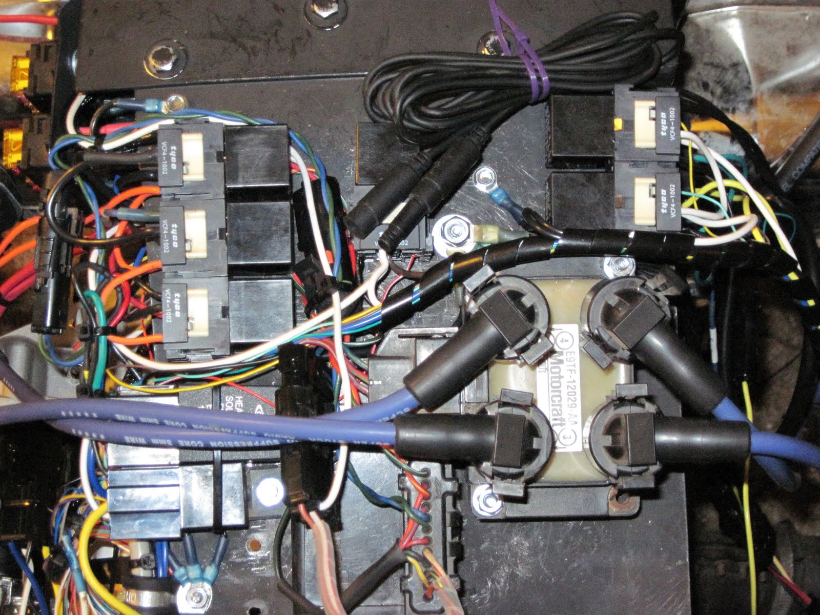

All in all, I have very little chassis wiring left before it's inspection ready. The alternator and N indicators are really optional, as is the tachomter (need some diodes to wire than in) and the speedometer sensor (front wheel; electrically very simple, but I'd like to hide the wiring to it as well as I can; it will be running down the chrome springer front end.

Tomorrow, a couple of mechanical issues and body wiring... Hopefully I won't have to stand and stoop the whole time!

Tuesday, May 25, 2010

Lights at the End of the Tunnel

I see them.

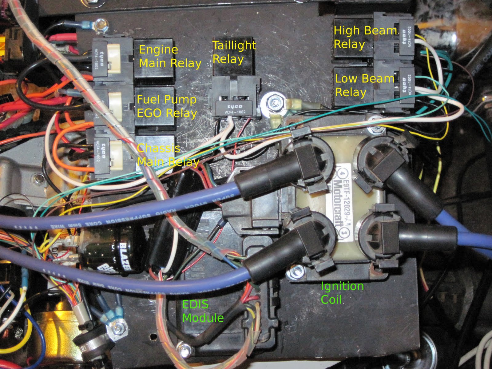
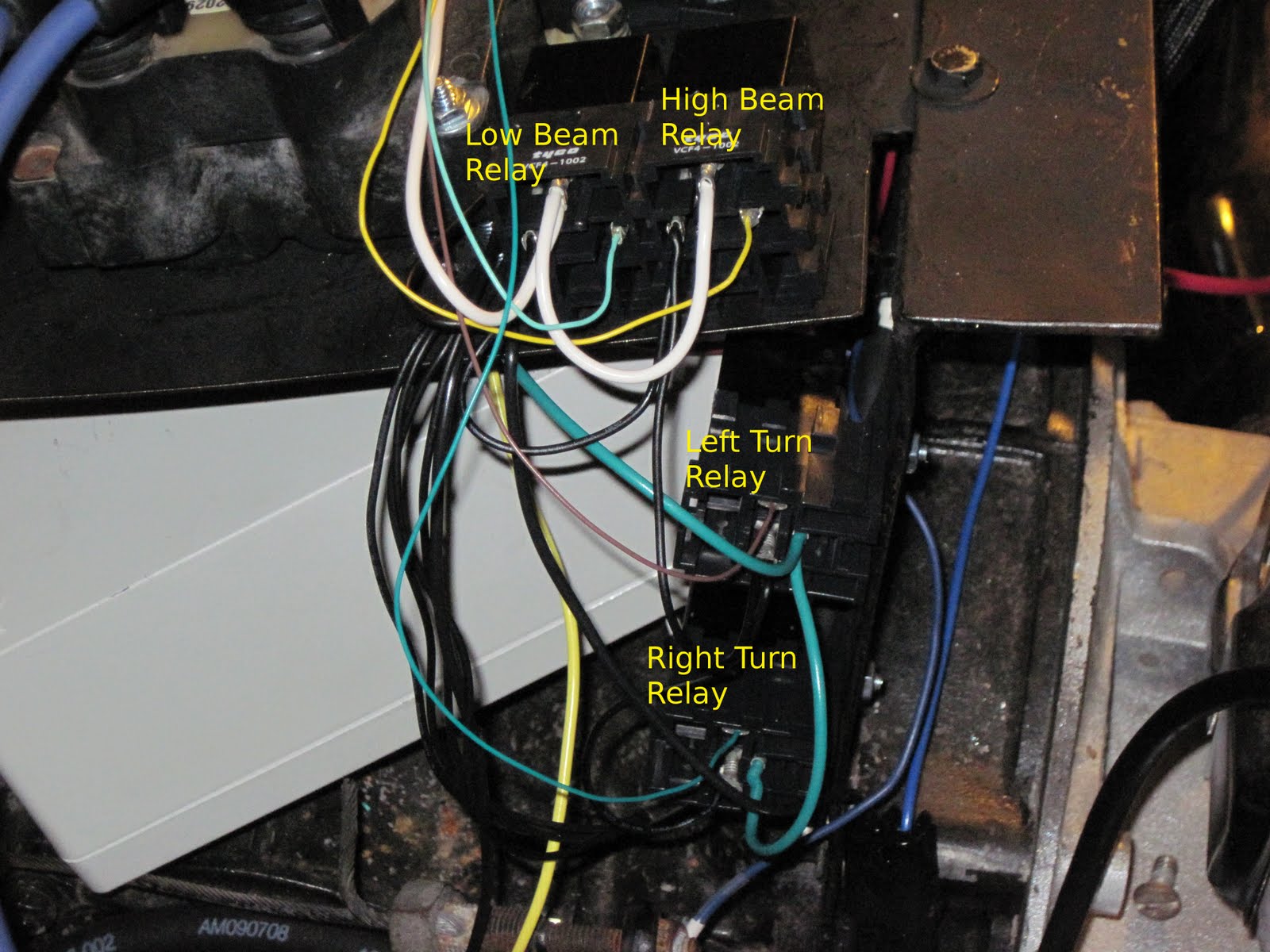
Tonight was mostly wiring relays, but that sounds deceptively quick and easy. I connected coil and power to 5 relays that control the headlight, taillights, and turn signals.


All these wires will be dressed up when I'm completely done!

I also wired the starter relay. It is zip-tied to the starter itself to save me room for another relay socket.

What's left to wire on the chassis:
front turn signals
speedometer sensor
connector or two to connect the relay outputs to the wiring for the body
brake light switch
horn relay and horn
a connector the license plate/trailer plug on the bumper
optional back up lights

I will then need to install the tail lights on the body and wire them and the headlight to a connector or two to mate the connectors on the chassis.

The hardest mechanical work left is to remove the fender brackets, though I will be putting the fenders on at a later date. Removing the brackets may involve removing the wheels. I also need to add spacers to lift the body so that it clears stuff it didn't used to clear, like the engine and the springs on the front end. That will mostly involve stacking washers or cutting wood blocks or something for four spots, but I will need to weld an extension on the frame tab under the seat.

That should have everything to the point where it can be inspected and become street legal for the first time since it was wrecked sometime in the '80's!

I need a proper permanent footrest, though that will doubtlessly need to wait until after the weekend.

Monday, May 24, 2010

Lots of Wiring

I had a good long chop at the trike on Friday night and all day Saturday. As is usually the case, I got a lot done but less than I'd hoped.

I spent some quiet time Saturday morning finishing the connectors on the speedometer, switch pod and the cable connecting them to the rest of the trike. I am using small gauge wire and isolating switched circuits with relays so that I can have a small but most importantly multiconductor cable going to the handlebars. The switchpod has 10 or so wires and the speedometer has 12 or so. Because a few wires (power, ground indicators, etc) are shared between the two, I made the cross connections at the connectors on the frame side. This also lets me run a single  wire for each function from front to back and all the wiring that goes on the body can jump to the body back there.

I also installed said speedometer and swtich pod....


This unit was chosen because not only does it display speed and mileage, but also engine RPM, fuel level (though I have not yet found and installed a fuel level sender; I will!), time and it has indicator lights for left and right turn, high beam, hazard, neutral and oil pressure.


I have something to connect to each of these indicator light. Turn, highbeam and oil will be as labeled. I will be substituting the alternator light for the hazard light, which I suppose indicates some sort of hazard. There is no neutral indication on the VW transaxle, but I think I will connect that light to the unused FIdle output in MegaSquirt and map it to indicate something useful, something like warmup or redline.

As a mildly interesting side note, all indicators except N and OIL light when power is applied. The N and OIL lights need ground to light. This works out in my favor on OIL because the oil pressure switch does indeed grounds when oil pressure is low and the FIdle output can be programmed for either, but by default, it grounds when active.

The two things that ended up delaying the most were rearranging the relay mounting locations to clear the slanted bit of the bodywork and wiring the fuse blocks.

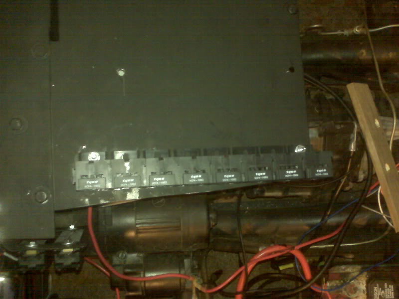
I cut the panel shorter and am now rearranging relay sockets so that they clear the edges, clear each other and still have room for the relay to be replaced in the future. Way back when, the plan was that all the relays would fit in a nice straight line....


... but there just isn't room to clear the back of the driver's seat. There are now going to be relays all over the place. Oh, well. Reality bites.


Please note that the chrome ignition switch is only temporarily installed here.

I found, not surprisingly, that a two or three pin flasher will fit in one of my relay sockets. On one hand, it keeps a consistent look to all the wiring, but it also means I have added a socket when I really needed to lose one. :)

I also found, not surprisingly, that my turn signal relay is not enough load to operate the flasher properly. There are a couple of possible solutions. Arguably the best is to use a flasher made for LED lighting, which is not load sensitive and should flash a relay exactly as well as a light. They have been hard to find locally. I needed some more connector pins so I ordered them as well as a suitable flasher from DelCity.

The fuse panel wiring became needlessly complicated because of my own short sightedness. I originally wired all 8 fuses to switched power, forgetting that a few things, such as the actual ignition switch, need fused but continuous power, so I had to wire the fuse panel feeds a second time, four switched and four non-switched. Then I remembered that I wanted a separate power feed from a switched relay to so that a short in, for example, the brake light wiring wont blow a fuse that feeds the engine. To feed that relay, I needed a separate fuse, so I stole the top fuse on the panel, only then to realize that I had wired the top 4 as switched.

After all the connector moving and reterminating, I now have a main chassis fuse, 3 non-switched fuses and 4 switched fuses. Should be plenty.

The project is coming down to the wire. It will be tough to get everything left to do done in three available evenings this week so I can get an inspection on Friday and have it driving on the weekend. I can only try!

Friday, May 21, 2010

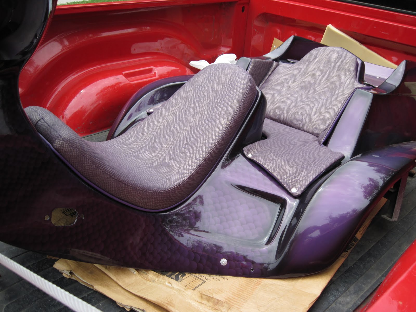
Upholstery Done!

If you saw the pic I had here before, you will recognize that, even sitting in the back of the truck, this is a much better picture, showing some of the snakeskin texture.


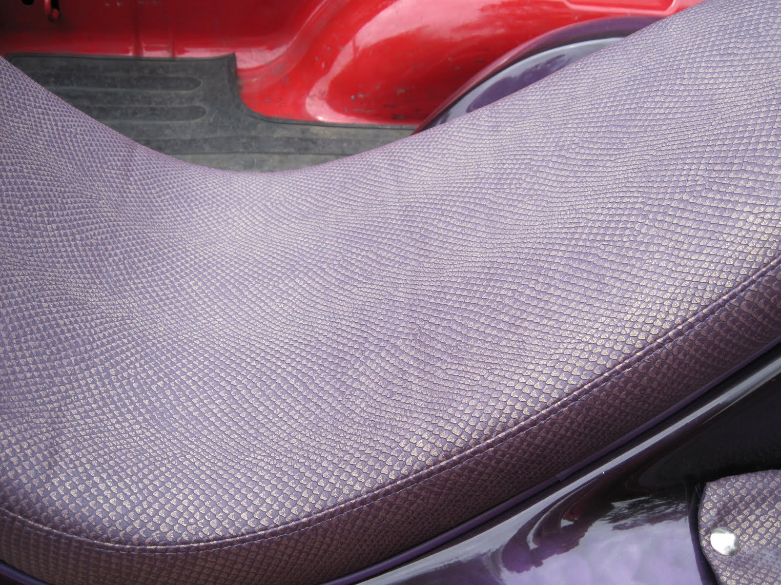
Here's a closeup of the seat itself.


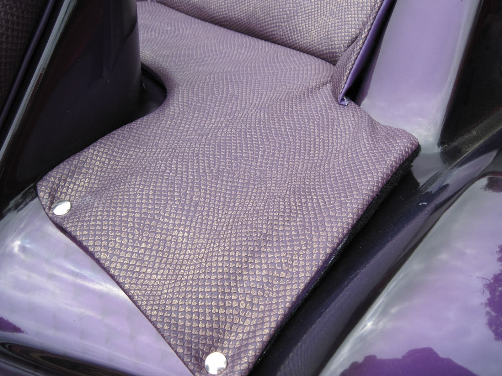
A little detail of the back seat...


All that's left to do is the rest of it!

Thursday, May 20, 2010

Chassis work begins

The engine is running and there's not much tuning I can do with it until the trike is on the street. I did manage to install a fuel pressure gauge for help troubleshooting. Besides, it looks cool.

While I was typing this, the trim shop called and the upholstery is done! It will be tomorrow before I can get by there, but I'm excited about it...

I am working on chassis tasks, including chassis wiring. The nerve center for the rest of the wiring is the speedometer and the handlebar switch. The speedometer also has odometer, tachometer, fuel gauge, clock, and six indicator lights, all of which are spoken for. The handlebar switch has switches for headlights, high beam, turn signals, horn and a momentary kill switch that I am going to use for the starter. Between these two units, there are 20-someodd wires that need to go *somewhere*. Since they both mount on the handlebar, I started there.

You may recall that the trike appears to have been in a wreck somewhere in it's distant past. The handlebar was bent in that collision. I'm not 100% sure which, if indeed either, of the two bars is in unbent condition, but I elected to pay my attentions to the righthand and make it match the left.

I must apologize for not getting a 'before' picture. Using my newly acquired torch, I heated the lowest bend as evenly as I could and lifted the bar to match the left. This left the upper section slightly higher than it's mate, so I heated the middle bend and pressed down to match the left. Then, viewed from the driver seat, the end of the grip section was pointed downward. I again heated the middle bend, but this time imparted a twist rather than a simple bend until the two match as closely as I can judge.


Please ignore that the bars are not mounted straight on the forks. That joint is not important to this particular operation. It will be important when it's on the road, just not yet.

I then layed out the location for the speedometer and cut a piece of 1/8" mild steel, shaped to fit at an angle between the bars and brazed in place.


While I hope to eventually re-chrome the bars, for now they just need to look better than this, so I sanded them to rough up the old chrome a bit, cleaned it with acetone and applied the same two part Krylon X-Metal treatment as I've used on the engine trim pieces.


Tuesday, May 18, 2010

Upholstery Finally Underway

Due to delays I wont bore you with, the body was finally delivered to Chris' Trim Shop this morning.

This Blackberry photo does the material no justice, but this is the stuff I finally decided on.


Sorry about the dust....

Perhaps more importantly, I have the engine running! 

Thursday, May 6, 2010

Getting Ready for Upholstery

The first thing I did tonight was get the body ready for transport to Chris' Trim Shop for upholstery tomorrow. I go get my material and drop both off for the work.

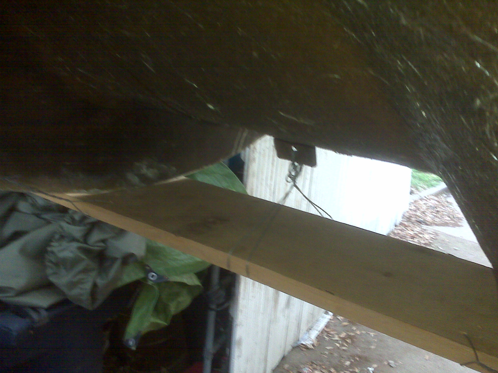
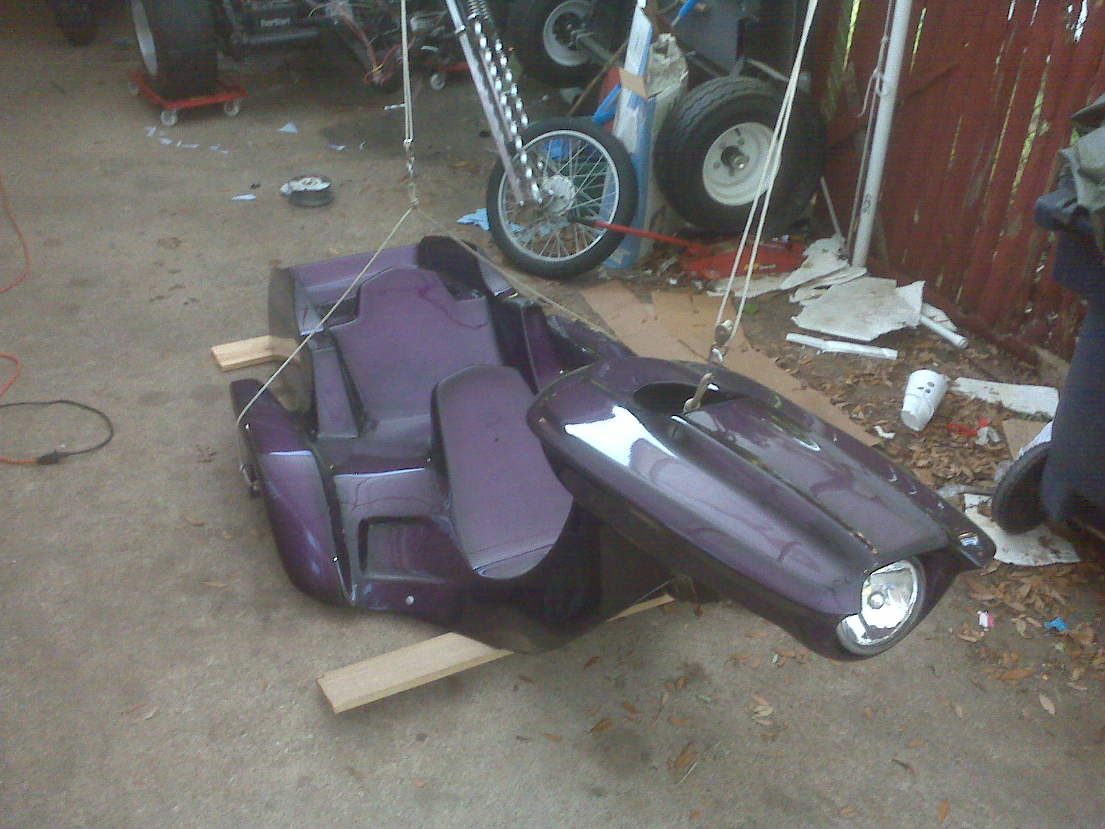
To protect the four "corners" that generally hit the ground first on the body, I wired and bungied a couple of boards to the low points.

The front still sat a little low, so I added a spacer to the bottom of that board, not shown here.

The board in the back is held on with a couple of ball cords laced through the tail light holes.

Now the body will be easier to handle with somewhat less fear of scraping the gorgeous paint job.

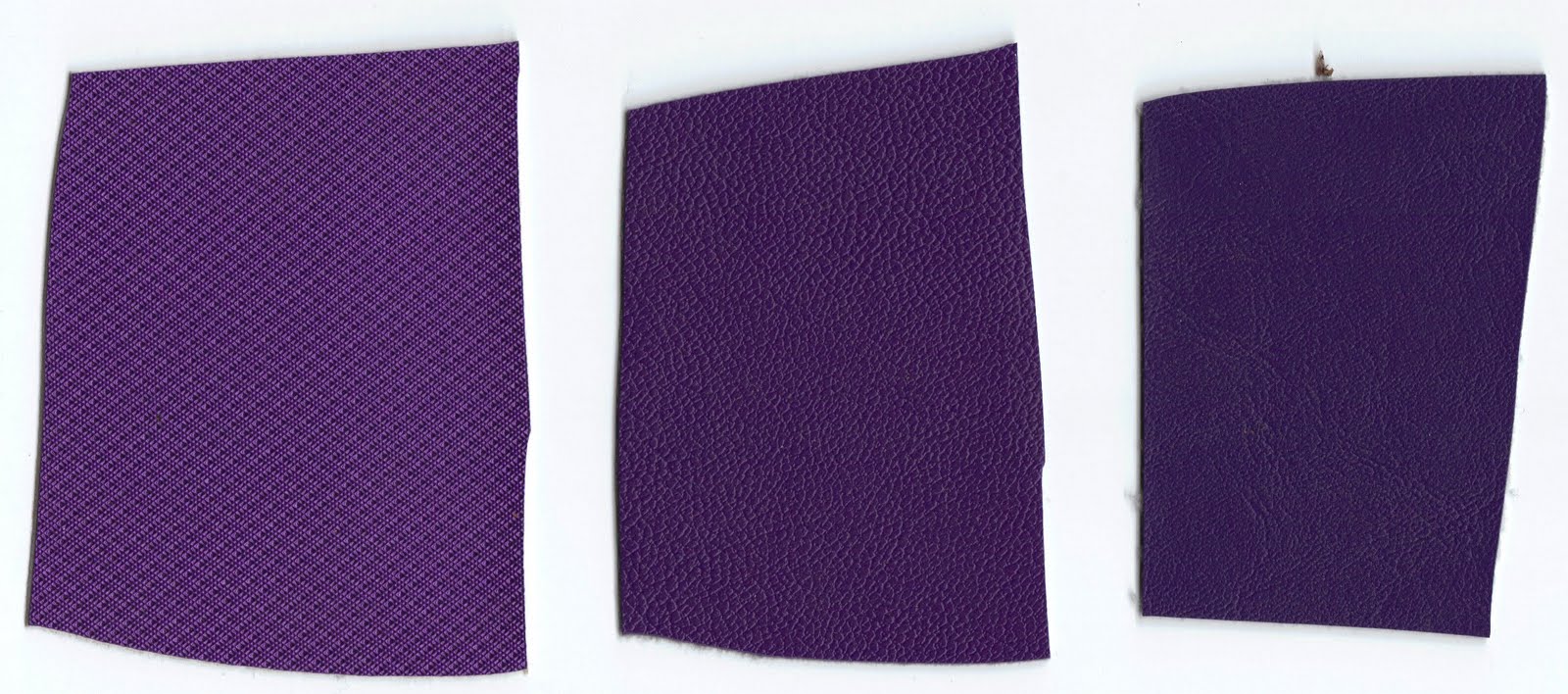
As for the upholstery, it's pretty much a tossup between the left and middle choices. Since it's only a couple yards of either, the fact that they are also the most expensive two is kind of incidental, $14.50 and $23.25 per yard, respectively.


It seems to me that the left one picks up the brighter tones of the paint better and it appears to me to be the heavier of the two, so it may well win.

The other option, available from the trim shop directly, is a black covering that has a snake or lizard skin texture, which I think is pretty cool for a dragon themed trike. I found something similar in purple on the internet, but it was so cheap per yard, I figured it probably not good enough quality.

So, unless something really cool jumps out at me, it will probably the the left one above.

Followers